

Why we obsess over insulation testing for our IR lamps
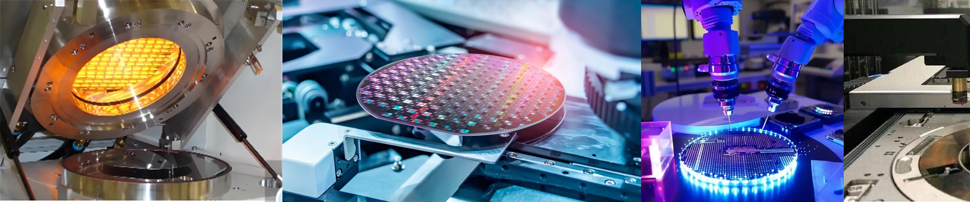
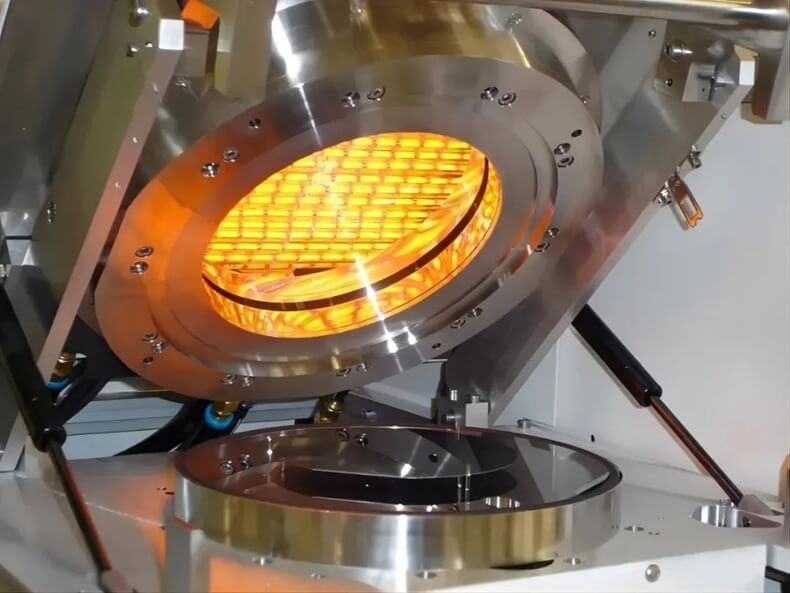
We test every single lamp tube that leaves our shop. Every one. No exceptions. When you’re dealing with smart sensor packaging or high-speed infrared lines, a tiny electrical leak is a nightmare. It isn’t just about a blown fuse. We’re talking about fried control boards or a ground fault that brings your entire production line to a screeching halt. That’s a lot of downtime you just don’t need. Pushing the limits Here is how we handle the “dielectric withstand” part. Basically, we hit the lamp with a high-voltage stress test—way higher than what it’ll actually see in your machine. Why? Because we want to find the weak spots now. If there’s a microscopic crack in the quartz or a bit of contamination on an electrode, it’ll arc right here in our lab. We’d much rather catch that spark on our bench than have it happen inside your equipment. Keeping the current where it belongs Then there’s insulation resistance. We check for any “leakage” between the energized parts and the chassis. In tight sensor setups, space is a premium and the heat is intense. If the insulation is weak, you get these annoying parasitic currents. You’ll start seeing “ghost” signals in your sensors, and suddenly your process stability just vanishes. It’s frustrating and hard to troubleshoot. A quick reality check Strict testing stops “infant mortality”—those annoying lamps that fail the moment you plug them in. You get a consistent electrical footprint across a thousand units. But here’s the thing: we can guarantee the lamp is solid, but your field wiring has to keep up. If you’re using cheap wires or loose terminals, the lamp’s internal safety can’t save you from a short circuit at the junction box. Make sure your connectors are rated for the same spikes the lamps are. We don’t do “batch sampling.” We don’t just test a few and hope for the best. We test everything so you get a component that actually handles the voltage of your shop floor.